
Why saved geometry alone is not enough
Teams often recreate a section by eye: set a view, make a new crop, then rotate the UCS until tracing feels correct. The result may be close, but it is not necessarily the same cut. Small changes in plane position, normal direction or depth can move apparent edges and produce inconsistent plans, elevations and clearance checks.
Section management solves a coordination problem. The Section Manager treats the spatial plane, point-cloud crop, section parameters and UCS as one reusable definition. Applying that definition restores the evidence view and the drawing plane together in AutoCAD or BricsCAD.
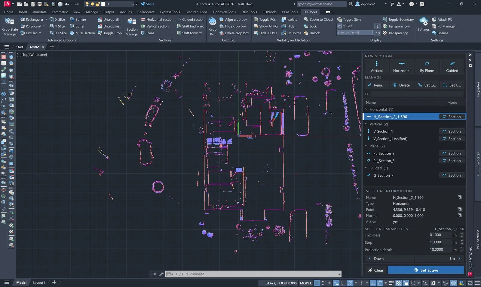
The components of a controlled section
| Component | Why it matters |
|---|---|
| Plane point and normal | Fix the cut’s location and viewing direction. Reversing the normal can reverse projection depth and orientation. |
| Thickness | Controls the point band included around the plane. It balances continuity against edge clarity. |
| Projection depth | Defines how much geometry behind a plan or elevation plane contributes to the view. |
| Step | Provides a controlled increment when examining adjacent levels or stations. |
| UCS | Aligns drawing coordinates with the section so tracing and measurement occur in the intended plane. |
| Crop box | Makes the spatial extent visible and editable, helping reviewers understand what has been included. |
Choose a slab for measurement, a projection for representation
A section slab is centred on the plane and includes half its thickness on either side. It is appropriate for cross-sections, level checks and geometry that should be read close to one plane. A projection includes points from the plane in one direction to a set depth. It is appropriate for plan and elevation drawings where features behind the cutting plane must remain visible.
Do not increase slab thickness simply to make a plan look fuller. That merges objects from different depths. If the deliverable represents depth, use projection mode and document the projection limit.
Organise sections around deliverables
Section lists work best when names communicate location and purpose. A practical pattern is Type_Location_Purpose, for example H_L02_FloorPlan, V_GridC_Facade or P_RoofSlope_Clearance. Grouping by horizontal, vertical, plane and guided type helps navigation, but naming should still make sense when exported to a review register.
Use separate definitions when two deliverables require different depths or thicknesses, even if they share the same plane. Changing a production section to satisfy a temporary inspection view weakens traceability.
Checks before a section becomes a reference
- Plane: verify the cut against controlled levels, grids, alignment or surveyed geometry.
- Normal: confirm the viewing direction and which side a projection includes.
- Density: check that thickness produces continuous evidence without excessive depth blur.
- Extent: inspect the crop box around the full area used by the deliverable.
- Coordinates: activate the stored UCS and verify origin and axis direction before tracing.
- Reapplication: clear the view, apply the saved section again and confirm the same crop and orientation return.
Working with Section Manager
- Create and validate a horizontal, vertical, plane or guided section.
- Open
PCSECTIONMANAGERand name the section according to the project convention. - Use Set active when crop, editable box and UCS must return as one coordinated state.
- Use Set Crop or Set UCS only for deliberate partial restoration; this is useful for comparison but should not be mistaken for the complete controlled state.
- Adjust thickness, step or projection depth in the panel while inspecting the scan, then repeat the quality checks.
- Use
PCSECNEXTandPCSECPREVfor controlled movement along the active section normal.
Clear removes the active marker; it does not uncrop the cloud. Use PCUNCROPALL when the display crop itself must be removed. PCSECTIONMANAGERCLI provides the command-line equivalent for scripted or panel-free workflows.
Common failure modes
| Observation | Interpretation and response |
|---|---|
| Tracing is offset after recall | Only the crop or only the UCS was restored. Reapply the complete active section and verify the saved plane. |
| An elevation contains unrelated background points | Projection depth is too large or points are being included from the wrong side of the normal. |
| Edges look doubled | The slab is too thick for the geometry and scan incidence angle. Reduce it while monitoring continuity. |
| Several sections appear identical | The names do not expose location or purpose. Check plane coordinates before consolidating or deleting records. |