Build and edit 3D pipework inside AutoCAD using dedicated tools for point-cloud fitting, editable LINE centerlines, elbows, T-joints, reducers and flanges. Move between editable LINE centerlines and native solid cylinders without leaving your drawing.
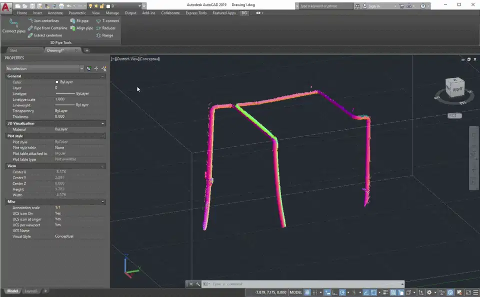
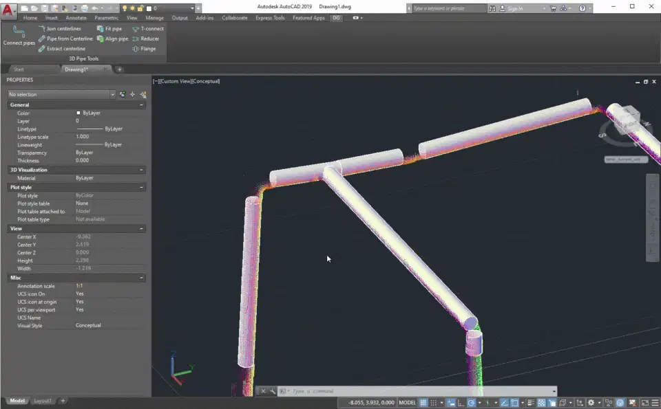
Use AutoCAD point-cloud centerline extraction, pick the visible pipe radius once, then build multiple solid cylinders along scanned pipe segments.
Extract LINE axes from existing pipe cylinders, edit or join them, then rebuild solid pipes from the corrected editable LINE centerlines at a chosen radius or diameter.
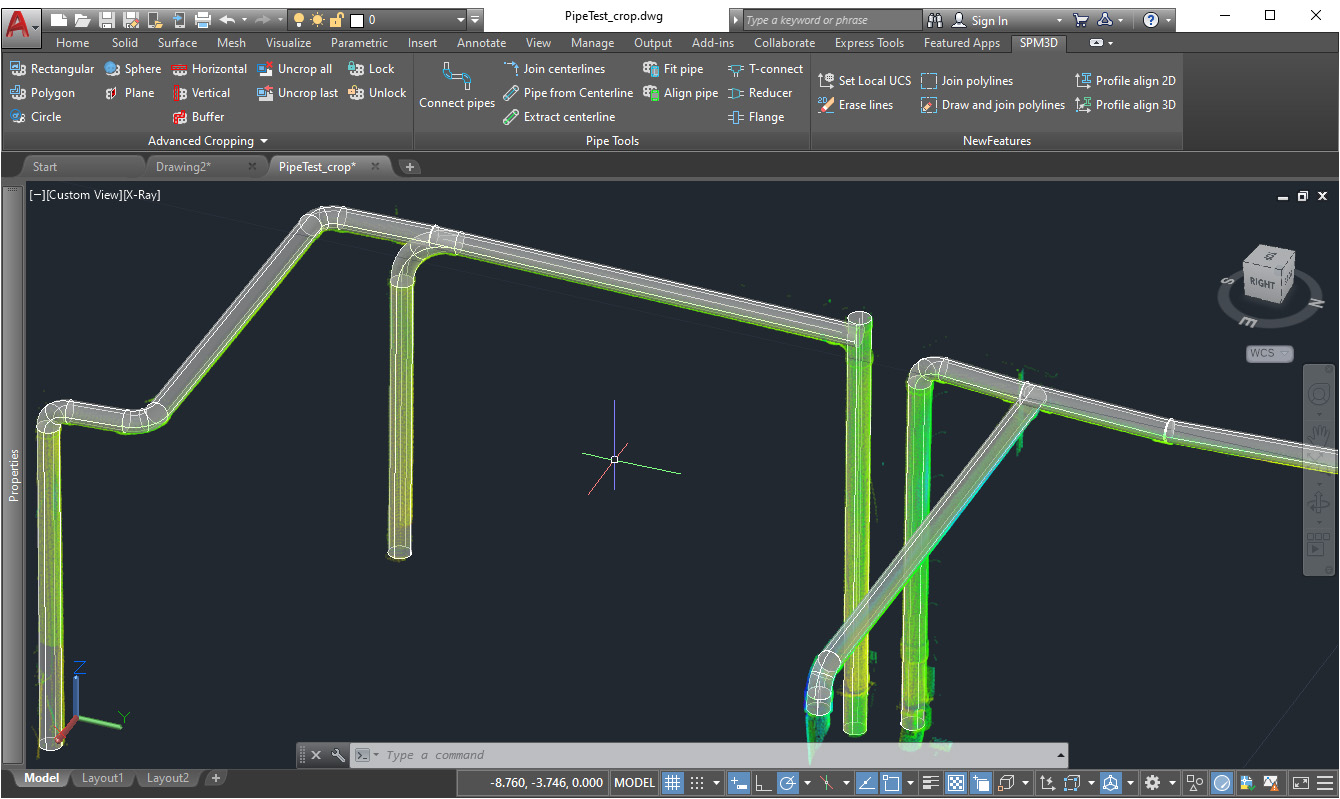
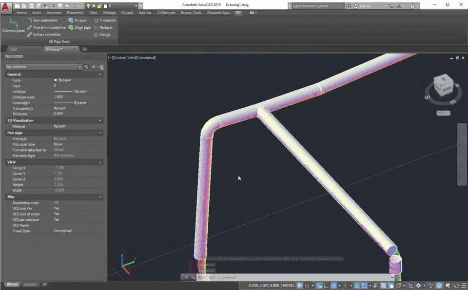
Connect a run of cylinders with smooth swept elbows or segmented lobster-back bends using short, long or custom bend-radius multipliers.
Select two pipes in any order. The tool determines the main and branch runs, then rebuilds the branch so its endpoint meets the main centerline.
Loft concentric or eccentric reducers between pipe ends and insert automatically sized disc flanges perpendicular to a pipe axis.
Align the UCS to a pipe cross-section for accurate modelling, and join non-coplanar editable LINE centerlines at their closest-approach point.
3DPfit uses AutoCAD's point-cloud centerline extraction, then builds solid cylinders at the radius you pick from the visible cross-section. Continue through multiple segments without repeating the radius setup.
Extract axes from pipe cylinders with 3DPCL, correct or extend the LINE centerlines, join gaps with 3DPJcl, and rebuild the pipes with 3DPfcl.
Select the pipe cylinders in run order and choose smooth or segmented elbows. Straight segments are trimmed and rebuilt automatically around short-, long- or custom-radius bends.
Dedicated fitting commands position branch endpoints, loft between different pipe diameters and create flange solids from the selected pipe dimensions.
The workflow produces ordinary AutoCAD 3D solids and LINE entities. Edit, dimension, copy, loft, sweep or hand them off using the CAD tools your team already knows.
Extract a centerline from each scanned pipe segment with 3DPfit, define the pipe radius from the visible cross-section, then connect the resulting cylinders with smooth or segmented elbows.
Sketch or extract LINE centerlines, correct their endpoints with standard AutoCAD tools or 3DPJcl, rebuild the cylinders, and add T-joints, reducers and flanges.
Nine focused commands cover pipe alignment, point-cloud fitting, centerline conversion, run connection and fitting construction. Results remain native AutoCAD geometry throughout.
Move from scanned pipe points to connected native AutoCAD solids.
Manual, automatic and semi-automatic methods.
Read guideSkew lines, smooth or segmented elbows and branches.
Read guideComplete pipe runs with additional native solids.
Read guidePick the single-plugin plan for this workflow, or step up to the full CADTools Suite for access to the whole toolkit.
Focused access to this plugin when you only need one workflow.
Best value when this plugin is the main tool in your production workflow.
Add the rest of the CADTools ecosystem when your projects span several workflows.
The most complete option for teams moving between point clouds, terrain, BIM and modelling work.
3D Pipe Tools supports AutoCAD 2021-2027 and AutoCAD-based verticals, including Civil 3D, Map 3D, Architecture, MEP, Mechanical, Electrical, Plant 3D and Advance Steel, on 64-bit Windows.
The tools create native AutoCAD 3D solid cylinders, swept elbows, segmented elbows, lofted reducers, flange solids and LINE centerlines.
3DPfit uses AutoCAD's PCEXTRACTCENTERLINE on a selected cloud segment. You then draw a circle over the pipe cross-section to define the radius, and the tool builds a cylinder along the extracted axis.
Yes. 3DPconnect can create either a smooth fillet-swept elbow or a segmented lobster-back elbow with between 2 and 30 miter segments.
Yes. Use 3DPCL to extract LINE centerlines from cylinders, edit them with standard AutoCAD commands, optionally join skew lines with 3DPJcl, then rebuild cylinders with 3DPfcl.
Yes. The CADTools Suite includes 3DPTools, PCCTools, DTMTools and FPTools from €99 per month or €999 per year.
Questions about 3D Pipe Tools or the wider suite? Send a message and we'll get back within one business day.