Quick answer
In AutoCAD and BricsCAD, PCCTools creates sections as controlled crop slabs. Use PCHSECTION for plans, PCVSECTION for elevations, PCPLSECTION for arbitrary surfaces, PCGSECTION for repeated cuts along a route, and PCMULTISECT when every station of that route should stay visible at once.
Each saved section can retain an oriented crop box and a named UCS. This makes the section repeatable and gives you a useful drawing plane for tracing or checking geometry.
Horizontal sections for plans and levels
- Run
PCHSECTION. PCCTools switches to a front view so the elevation can be selected. - Pick the required Z level and adjust the slab thickness when needed.
- PCCTools applies the crop, creates an editable box and switches to a top view.
- Set the saved section UCS current to draw directly at that level.
- Use
PCHSNEXTandPCHSPREVto step through adjacent levels.
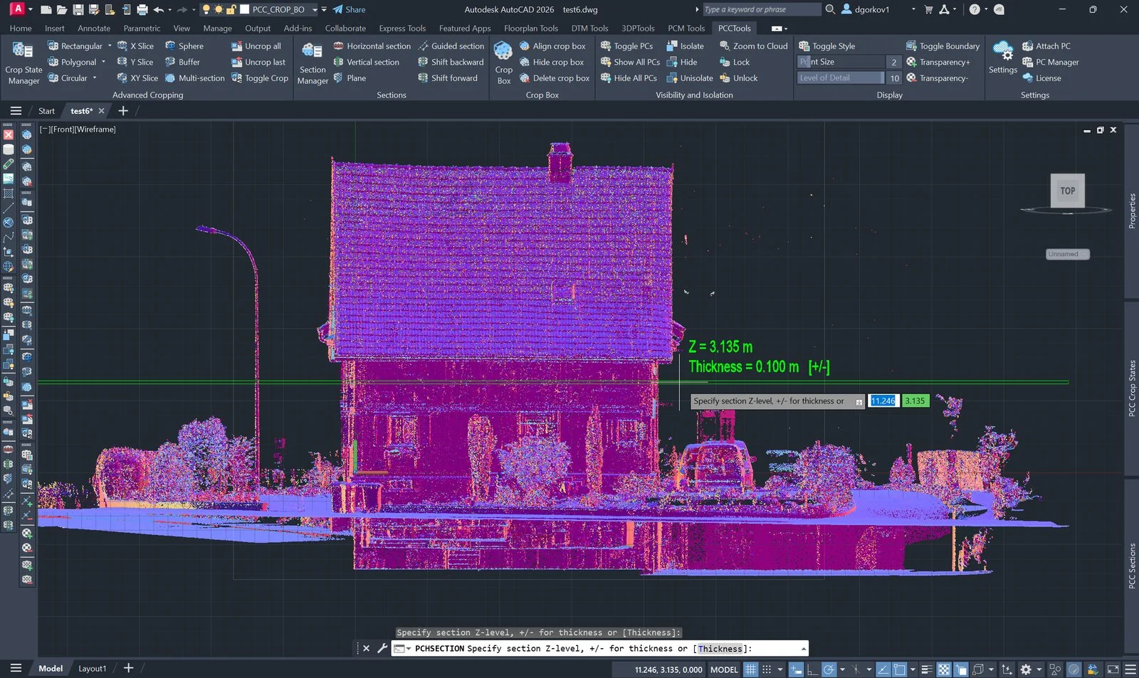
PCHSECTION in Front view: the slab previews at the cursor elevation, labelled with the Z level and the current thickness. Press T at any point to change the thickness before picking.Vertical sections for elevations
Run PCVSECTION, draw the section line in plan and pick the facing side. A live slab and direction arrows clarify which points will remain.
- Pick the two endpoints of the section line.
- Set the thickness based on scan density and the detail required.
- Pick the facing side using the live direction preview.
- Activate the created UCS to look directly at the elevation.
Sections on sloped or arbitrary surfaces
PCPLSECTION can define the cutting plane from three picked points, a 3D face, or a detected flat region in the cloud. Detection samples the points within a fixed radius of the point you pick, fits a plane with a robust (RANSAC) algorithm that ignores outliers, then refines it by least squares on the inliers. The picked point seeds the fit, so the plane locks onto the surface you clicked even in noisy data.
From version 3.1 the slab thickness is asked for after the plane is defined, and the slab is drawn live on that plane, so it can be sized against something visible. The crop is applied immediately: inspect it, then name the section to save it, or press Esc to discard it and pick again.
When to use Detect: roofs, ramps, slabs, tanks or other flat surfaces that are not aligned with the world axes.
Repeated cross-sections along a route
Use PCGSECTION to walk a perpendicular section along a line or polyline. Define the guide path, station step and slab thickness, then move the cut with PCGSNEXT and PCGSPREV.
This is useful for roads, tunnels, channels and linear infrastructure where sections are needed at consistent intervals.
Every station at once: multi-section
Where a guided section shows one cut at a time, PCMULTISECT crops the cloud to a comb of evenly spaced slabs along an axis and keeps all of them. Define the axis, set the corridor width, adjust the count and thickness against a live preview, then accept. It is the faster route to a complete set of road, channel or tunnel cross-sections; the step commands remain the right choice when each station is inspected in turn.
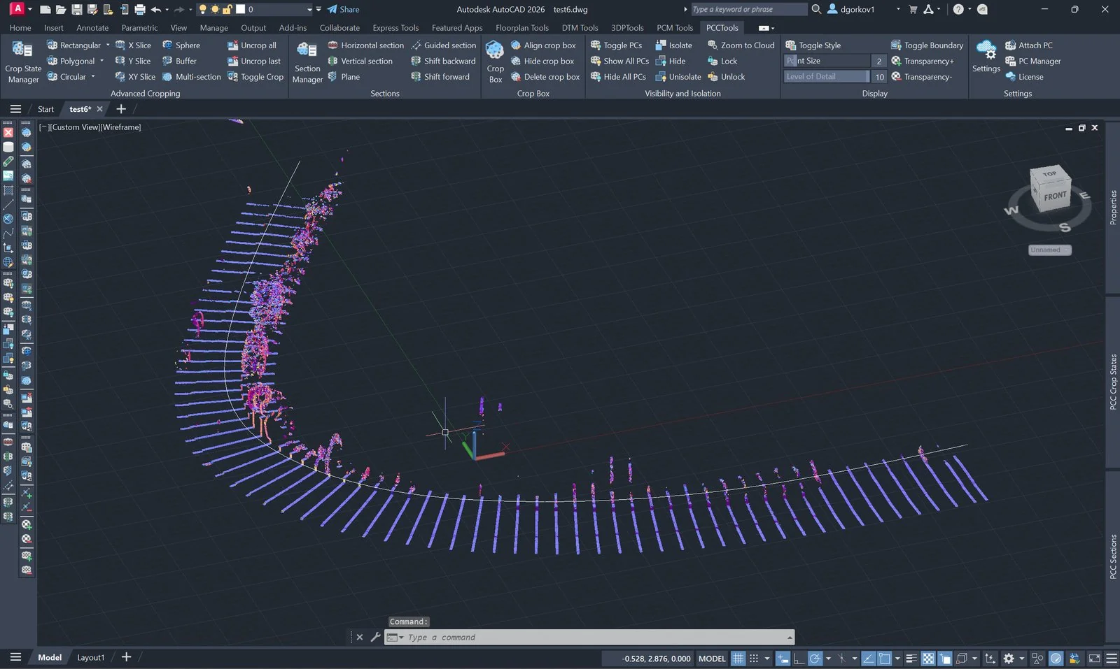
PCMULTISECT along a curved axis. The full workflow and the live adjustment keys are in the multi-section guide.Recall sections with the Section Manager
Creation defines the cut; management keeps it reliable through review and revision. The dedicated Section Manager technical article explains how plane, crop, UCS, thickness, step and projection depth should be governed as one section definition.
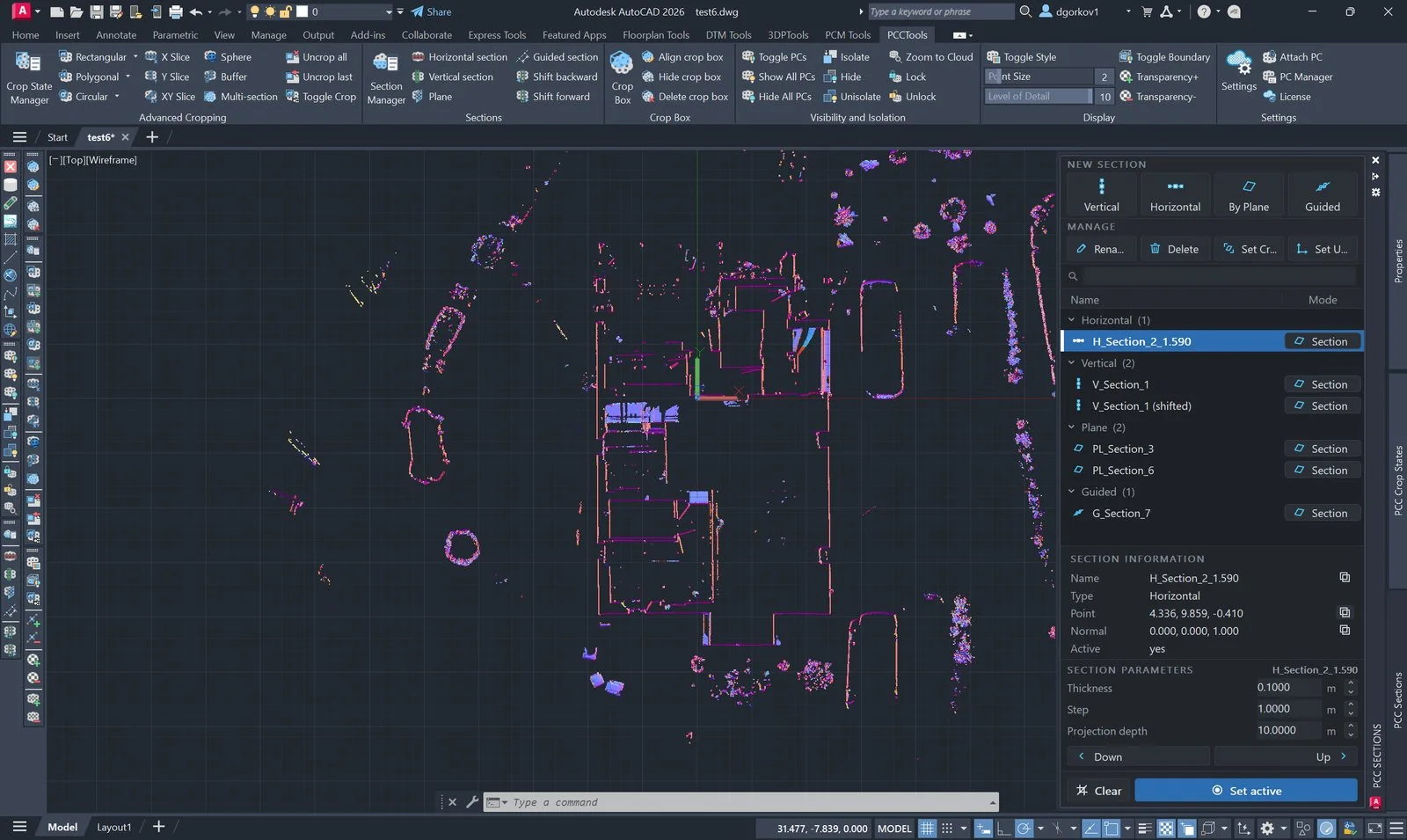
PCSECTIONMANAGER opens the dockable Sections panel. Sections are grouped by type, and the selected section’s plane point, normal and parameters are shown below the list.
- Set active is the whole move: it crops every cloud to the section, rebuilds the editable crop box on it and restores the section’s named UCS — without closing the panel.
- Set Crop and Set UCS split that in two, for when only one half is wanted: Set Crop cuts the clouds and leaves the UCS and the view alone; Set UCS moves the drawing plane onto the section without touching the crop.
- Clear clears the active marker only. It does not remove the crop; use
PCUNCROPALLfor that. - The New section row starts a vertical, horizontal, plane or guided section; Rename and Delete act on the selected one.
PCSECNEXTandPCSECPREV— the ribbon’s Shift forward and Shift backward buttons — step whichever kind of section is in force.PCSECTIONMANAGERCLIis the command-line equivalent of the panel.
Section parameters, without leaving the drawing
The foot of the panel carries the numbers you tune while working, for the selected section, in current drawing units: Thickness, Step and Projection depth. Editing one there re-cuts the section on screen, so a thickness can be judged against the points rather than guessed in a modal settings window. The shift row beside them moves the cut along its own normal — labelled Back and Forward, or Down and Up on a horizontal section.
Slab or projection
Each row carries a mode button that switches the section between the two things a cut plane is used for:
- Section — a slab centred on the plane: half the thickness in front of the cut and half behind. This is what you want for a cross-section or a level check.
- Projection — everything from the plane back to the projection depth, in one direction only. This is what a plan or an elevation drawing actually shows, and it is the mode to use when tracing a floor plan or a facade.
The mode travels with the section, so a plan projection and a slab section can sit in the same list and each stay what it is. Save a plan projection with vertical sections in PCCSETTINGS creates the projection alongside the slab automatically.