
Why a section series is a measurement framework
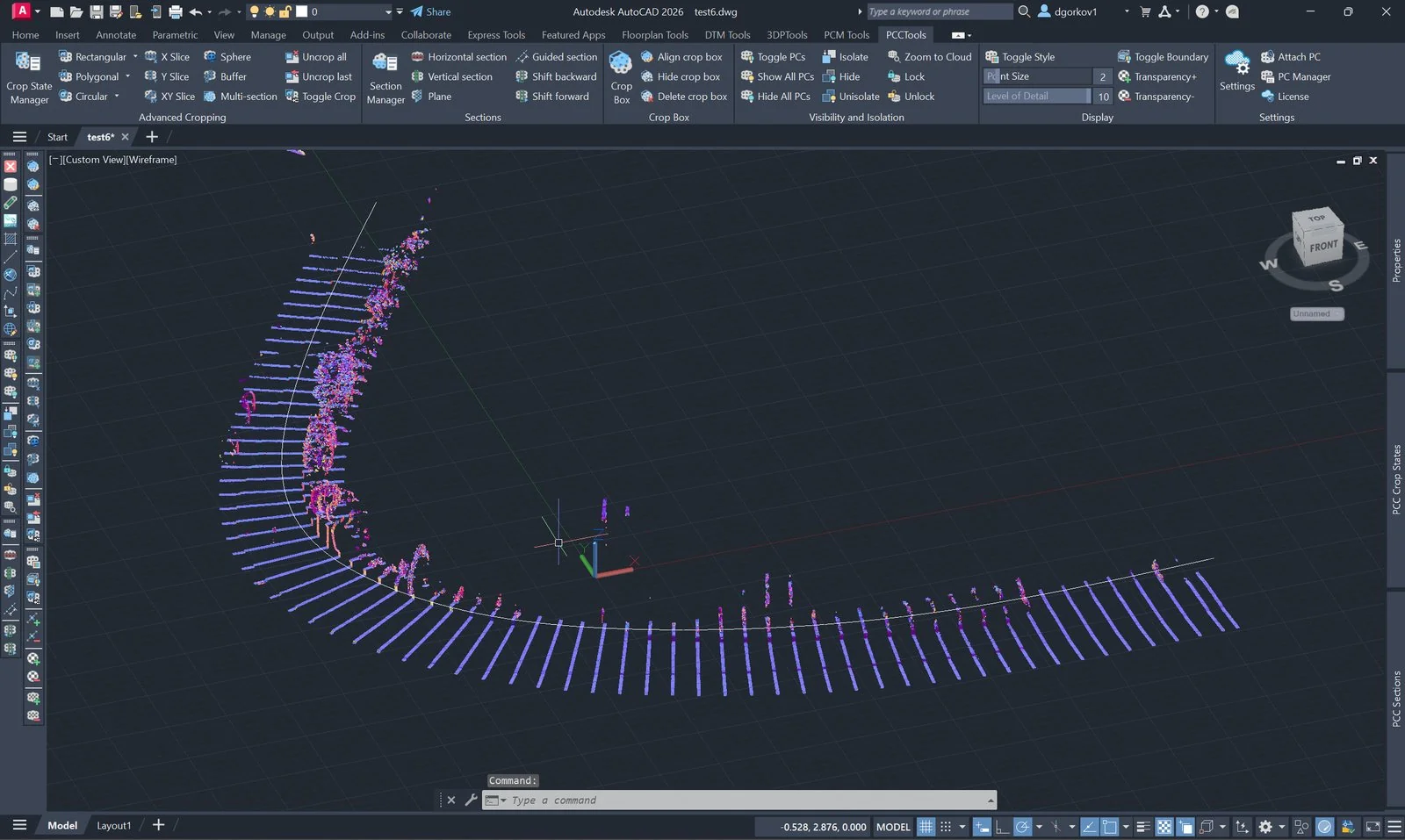
A road, rail corridor, tunnel or channel changes continuously. Individual ad-hoc cuts may look convincing, yet they cannot support reliable comparison when their positions, widths or thicknesses differ. A useful series therefore needs a stable axis, a documented station interval, enough width to cover the asset and a slab thickness appropriate to the point density.
Core principle: choose the sampling geometry from the engineering question and required deliverable, not from whichever points happen to be easiest to see. PCMULTISECT then applies that geometry consistently in AutoCAD or BricsCAD.
Four variables control the result
| Variable | Engineering meaning | Selection rule |
|---|---|---|
| Axis | The reference from which station position and local perpendicular direction are derived. | Use the project centreline or another controlled alignment. Avoid an improvised path when results must match chainage. |
| Spacing | The longitudinal sampling interval. | Start from the deliverable specification. Add local sections at breaks in grade, curvature, structures or other discontinuities. |
| Corridor width | The full cross-axis reach of every slab. | Cover the asset, verges and expected change zone. Centre the axis where possible so width is not wasted on one side. |
| Slab thickness | The depth of points projected into each apparent section. | Use the thinnest slab that remains continuous at the scan density. Excess thickness blurs edges; insufficient thickness creates gaps. |
Uniform spacing is useful because it makes change measurable, but uniformity is not a substitute for judgement. Sharp bends, junctions and structures usually need supplementary sections even when the standard interval is unchanged elsewhere.
One section at a time or the complete series
| Method | Best suited to |
|---|---|
PCGSECTION | Detailed inspection or tracing at one station, then stepping forward and backward along the route. |
PCMULTISECT | Coverage review, comparison of the whole corridor and a drawing that must retain every station simultaneously. |
A multi-section result is a crop geometry, not a named section record. Save it as a crop state when the complete comb must be recalled; use Section Manager when each cut needs its own controlled plane, UCS and parameters.
Quality-control checks before tracing
- Coverage: verify that every slab crosses the full asset and that no outside edge is clipped.
- Continuity: inspect sparse areas for holes caused by a slab thinner than the local point spacing.
- Orthogonality: check the source alignment around bends; small kinks can rotate consecutive sections unexpectedly.
- Performance: treat a very high section count as a design warning. More boundaries can slow display without adding meaningful information.
- Reproducibility: record the axis source, spacing, corridor width, thickness, units and any supplementary stations in the project QA record.
Applying the design in PCCTools
- Prepare or select the controlled line, polyline or arc that represents the axis.
- Run
PCMULTISECTin AutoCAD or BricsCAD and define the full corridor width. - Set the station count or exact spacing, then set slab thickness while reviewing the live preview.
- Confirm only after the first, last and critical bend stations cover the intended area. Existing crops are replaced, so preserve any required view as a crop state first.
- Save the accepted result with
PCCSSAVEwhen it must be recalled or audited later.
The preview controls are N for count, D for spacing and T for thickness; + and − adjust the active value. Above 500 slabs, reconsider the sampling interval before accepting the performance warning.
Common failure modes
| Observation | Interpretation and response |
|---|---|
| Outer edges are missing | The corridor is too narrow or the axis is off-centre. Correct the alignment or increase the full width. |
| The section reads as a fuzzy band | The slab is too thick for the required edge precision. Reduce thickness while checking continuity. |
| Some slabs are almost empty | Local scan density is lower than expected. Increase thickness or flag the coverage deficiency instead of interpolating unsupported geometry. |
| Display becomes slow | The series contains more boundaries than the decision requires. Increase spacing or split the route into controlled reaches. |